


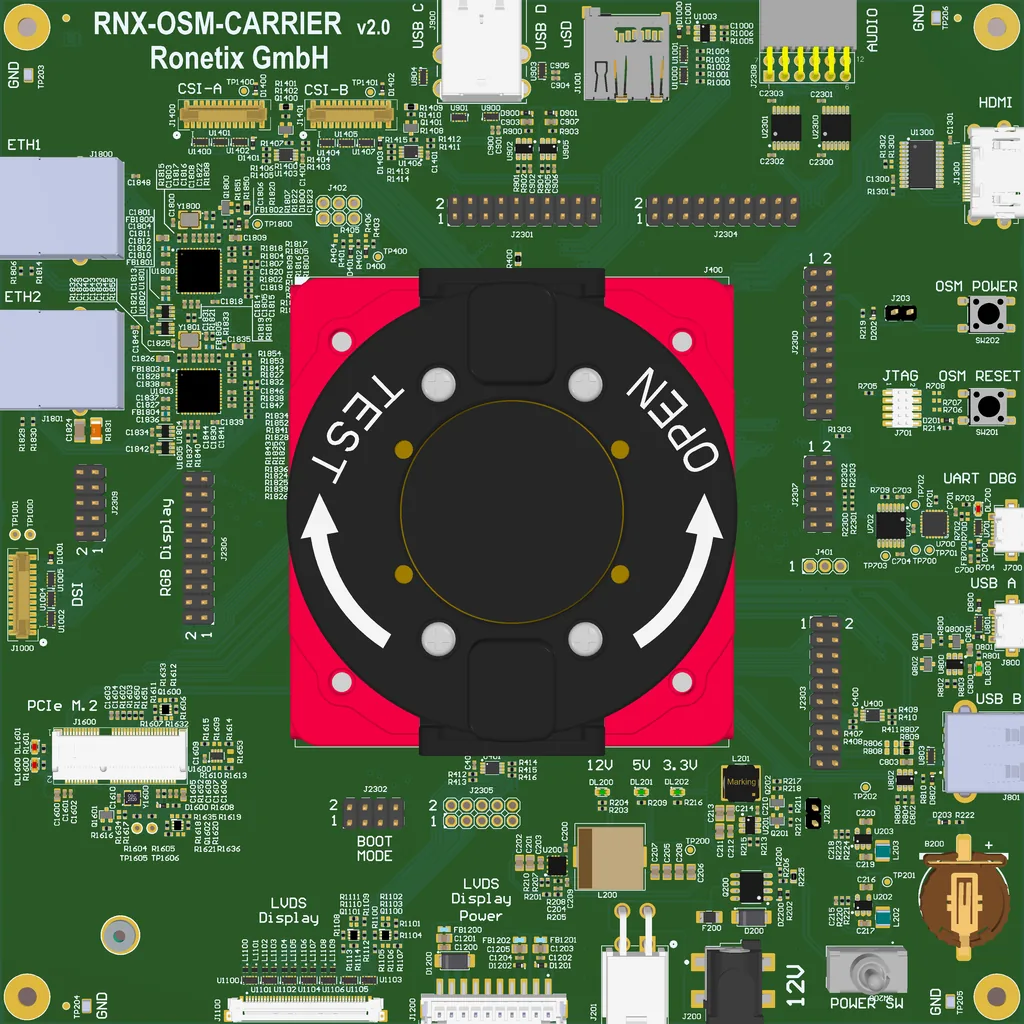
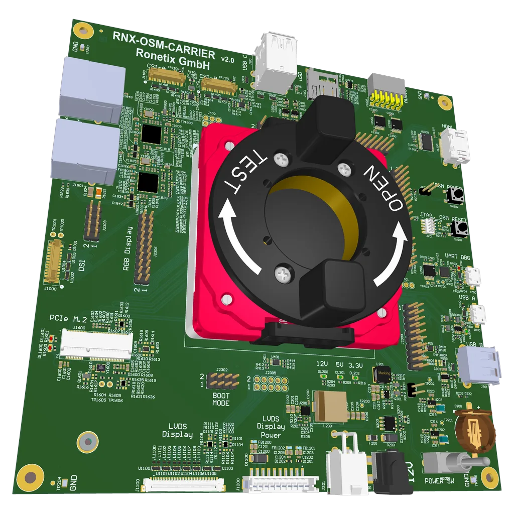
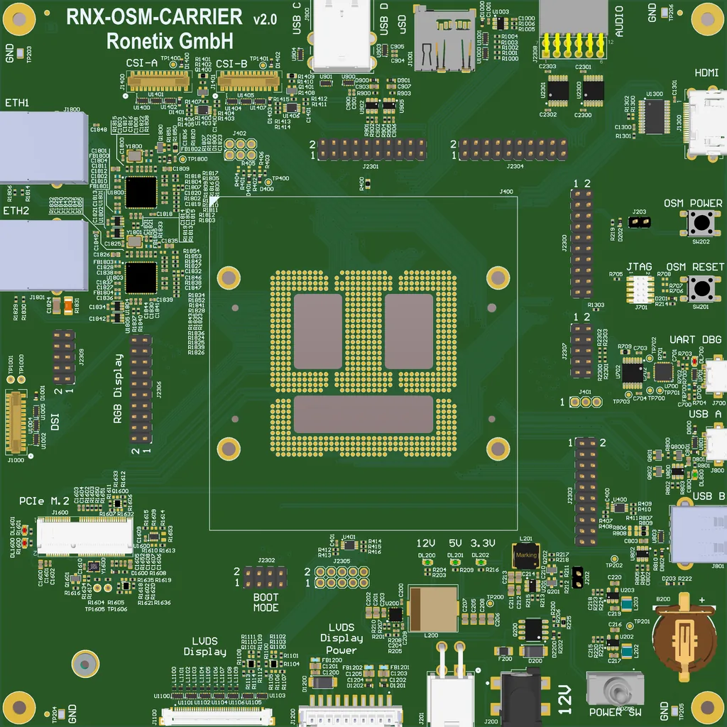


The RNX-OSM-CARRIER v2.0 board is designed for development and mass production test of SoMs in the Open Standard Module™ (OSM) v1.2 form factor, sizes S, M and L. The module is clamped in an LGA662 socket – modules are exchanged in seconds, without soldering.
Development and mass production test
For the mass production test of OSM modules, the module is inserted into the socket without soldering, and most module signals (UART, SPI, GPIO, CAN, ADC) can be verified with simple loopback jumpers on the 2.54 mm pin headers. The USB debug console is powered from the USB cable, so the test log is captured from power-up on.
Mating Products:
RNX-iMX93-OSM – SoM with NXP i.MX93
RNX-RZG2UL-OSM – SoM with Renesas RZ/G2UL/A3UL/FIVE
RNX-RZV2N-OSM – SoM with Renesas RZ/V2N
On the Carrier board, the following interfaces are available:
- LGA662 socket for OSM v1.2 modules, Size S, M and L
- 12 V power input: 2.1 mm DC jack or 4-pin Molex Mini-Fit; power switch
- 2x Ethernet 10/100/1000BaseT – RJ45
- USB-A: USB 2.0 OTG, micro AB
- USB-B: USB 2.0 Host, Type A
- USB-C, USB-D: USB 3.0 Host, stacked dual Type A
- USB debug UART_A and UART_CON, micro AB
- micro-SD card slot
- M.2 Key E connector (PCIe, optional USB 2.0)
- HDMI connector
- dual-channel LVDS display connector with display power connector
- MIPI-DSI 4-lane connector (Raspberry Pi CM4 pinout)
- 2x MIPI-CSI 4-lane camera connectors (Raspberry Pi CM4 pinout)
- RGB parallel display headers
- PMOD Type 7 (I²S) connector, e.g. for Digilent Pmod I2S2 audio
- JTAG/SWD, 10-pin 1.27 mm
- pin headers with UART, SPI/QSPI, I²C, PWM, GPIO, CAN and ADC
- boot mode jumpers, coin cell for the module RTC


 No products in the cart.